Computational Codes
Below is just a sample of our computational capability. For the full overview, you may download the complete document here.
- Reactor Design and Advanced Fuel Cycle
- MCNP5: Monte Carlo N-Particle version 5
- MCNP5 is a general Monte Carlo radiation transport code capable of transporting neutrons, photons, and electrons
through virtually any materialin various geometries. A versatile program, MCNP is being used in modeling nuclear criticality and
the design of space and terrestrial nuclear reactors and radiation shielding applications. ISNPS uses MCNP to analyze the
criticality of its space reactor designs to determine that they meet operational and safety criticality requirements. It is
also used for modeling shielding for neutrons and photons produced by reactors and radioactive sources.
- MCNPX: Monte Carlo N-Particle eXtended
- MCNPX is a three dimensional Monte Carlo code (computational tools) capable of treating charge particle transport using either
nuclear cross section data or nuclear model calculation. Current version is capable of treating many light particle such as: neutrons,
anti-neutrons, protons, anti-protons, photons, electrons, positrons, muons, anti-muons, electron neutrinos, anti-electron neutrinos,
positive pions, negative pions, neutral pions, short K-0s, long K-0s, positive kaons, negative kaons, deuterons, tritons, helium-3s,
and alphas. Therefore, MCNPX makES it possible to compute the radiation effects resulting from secondary particles produced by primary
particles interaction with shielding materials. ISNPS is currently using MCNPX to simulate solar proton radiation and computed the
particle fluxes (both for the primary and secondary, as the current version does not distinguish between the primary and secondary
particles), the total dose, and the displacement damage energy deposition. The tools allowed us to assess what kind of secondary
particles are possible, their relative fluxes, and a comparable view of different shielding materials. Such considerations will
be important for satellite design and risk assessment for astronauts in long-term exploration and habitat. However, this is just
one example of many possible applications of MCNPX particle transport code.
- ISNPS is currently evaluating several coupled monte carlo transport burnup packages for use in modeling reactor lifetime
reactivity changes and actinide waste management concepts. MonteBurns 2.0 couples together MCNP5 with the burnup code Origen2.2. MCNPX 2.6c
internally incorporates the CINDER90 burnup package within the code, simplifying its use. An in-house Simulink model used in conjunction
with MCNP for modeling lifetime reactivity changes in space reactors is also being evaluated. The three packages combine work in similar
fashions to model burnup, using the monte carlo transport code to determine the cross sections or reaction rates and feeding those rates
to the burnup code for handling the production and depletion of nuclides in the burned materials. Monte carlo codes such as MCNP provide
the capability to model virtually any system in almost any geometry granting great versatility to the packages. MonteBurns 2.0 uses MCNP5
to determine the one-group cross sections Origen2.2 requires as inputs to its models, while MCNPX 2.6c and the MCNP-Simulink model use
one-group reaction rates calculated by the monte carlo code to input into the burnup package. MCNPX 2.6c can also produce 63 group fluxes
for input to CINDER90 when the reaction rate cannot be calculated by the code.
- To determine which code is best suited for ISNPS's computational modeling efforts the three code packages are currently being
benchmarked against available experimental data from commercial pressurized water reactors. When the best suited transport-burnup package
is determined it will then be used to calculate the operational lifetime for the SCoRe-S family of reactor concepts. The package will
later be used to help model advanced fuel cycle concepts to support research in reducing the production of plutonium and other long-lived
actinides in commercial power reactors and aid in the destruction of existing actinide wastes and plutonium stocks to ease future radioactive
waste and proliferation challenges. Advanced mixed thorium oxide fuels, liquid metal cooled systems, and fast spectrum actinide burners are
problematic to model with dedicated thermal light water reactor codes making a more general modeling package capable of modeling systems of
almost any energy spectrum and material composition an invaluable tool for ISNPS's research.
- ORIGEN-ARP: Origen Automated Rapid Processing
- Origen-ARP is an isotopic depletion and decay analysis program designed to characterize nuclear fuel assemblies. Part of the SCALE package,
Origen-ARP provides for fast characterization of nuclear fuel under irradiation and decay conditions. ARP provides the Origen-S isotopic
depletion code with problem dependent 3-group cross sections for its burnup calculations, allowing the package to model almost any
commercial reactor currently in use. Origen-ARP is being used at ISNPS to study the behavior of MOX, (U,Th)O2, and inert matrix fuels
for use next generation commercial nuclear reactors in reducing the production of minor actinide, reducing the mass and the volume of
spent nuclear fuel.
- SCALE 5: Standardized Computer Analyses for Licensing Evaluation version 5
- SCALE is a modular code that couples together functional modules, such as transport or depletion codes, allowing for combined analysis to
be performed with a single code package. The program allows the user to use the same code package for handling neutronics, thermal, burnup,
shielding, and other interrelated analysis in a coupled environment. SCALE 5 contains the 3D Monte Carlo transport codes KENOV and KENOVI,
the burnup code Origen-S, TRITON, which links the 2D discrete ordinates code NWET with Origen-S, among many others. ISNPS uses SCALE for
studies involving commercial power reactors and advanced nuclear Fuel Cycle and fuel management applications.
- CFD Analysis and Simulation
- ANSYS
- ANSYS is a general purpose finite element modeling package for numerically solving a wide variety of mechanical problems. These problems
include: static/dynamic structural analysis (both linear and non-linear), heat transfer and fluid problems, as well as acoustic and
electromagnetic problems. In the past, obtaining all of the simulation capabilities needed for complex and demanding modeling scenarios
frequently meant combining several different software packages. ANSYS Multiphysics provides the analysis industry's most comprehensive coupled
physics tool combining structural, thermal, CFD, acoustic and electromagnetic simulation capabilities into a single software product. With
ANSYS Multiphysics, you are getting the entire ANSYS simulation suite in one convenient package! ANSYS Multiphysics integrates the power of
direct (matrix) and sequential (load vector) coupling to combine the appropriate "physical fields" required for accurate, reliable simulation
results in applications ranging from cooling systems, power generation, to biotechnology and Micro Electro Mechanical Systems (MEMS).
The software easily simulates complex thermal-mechanical, fluid-structural and electrostatic-structural interactions, and includes the
complete range of powerful ANSYS iterative, direct and eigenvalue matrix solvers. ANSYS Mechanical includes a full complement of nonlinear
and linear elements, material laws ranging from metal to rubber, and the most comprehensive set of solvers available. It can handle even
the most complex assemblies especially those involving nonlinear contact and is the ideal choice for determining stresses, temperatures,
displacements and contact pressure distributions on all your component and assembly designs.
- UNM-ISNPS developed and designed a novel, thermoelectric radioisotope power system for NASA's future space and planetary exploration missions
(Figure 1). This system will not only have a specific electric power greater than 12 We/kg, which is more than twice that of the
state-of-the-art GPHS Radioisotope Thermoelectric Generators (which power the Voyager, Galileo and Ulysses probes), but also an overall
efficiency greater than 14%. Such high conversion efficiency would halve the amount of plutonium dioxide fuel needed for a given electric
power requirement. The proposed advanced power system couples novel, segmented thermoelectric unicouples, based on advanced thermoelectric
materials developed at JPL, to one or several standard General Purpose Heat Source bricks, and would be easily scalable to meet missions
power requirement ranging from a few watts to hundreds of watts.
- During the course of this work, it was necessary to create and incorporate new numerical elements and new routines in the
very powerful ANSYS 5.7 finite elements software to extend the capabilities of the software for ultimately modeling the entire radioisotope
power system as well as the experimental setup. ANSYS has also been used at UNM-ISNPS to perform thermo-mechanical analyses of
non-segmented (Figure 2) and segmented multicouples for RPSs.
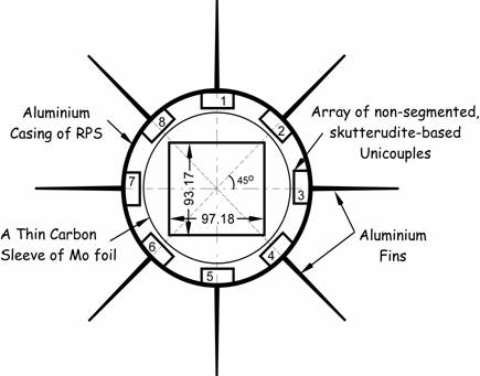
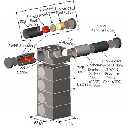
Figure 1. Skutterudite ThermoElectric Radioisotope Power System
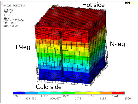
Figure 2. Temperature Contours and Displacements in a SiGe ThermoElectric Unicouple of a Power Conversion Assembly of a Jupiter Icy Moon Orbiter Spacecraft
- MATLAB/SIMULINK
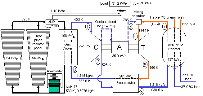
- ISNPS has developed a Dynamic simulation Model (DynMo-TE) of Space Reactor Power Systems (SRPSs) with Thermo-Electric (TE) conversion,
and is currently developing the DynMo-CBC for simulating the dynamic behavior of SRPSs with Closed Brayton Cycle (CBC) engines using the
SIMULINK® platform (https://www.mathworks.com/products/simulink). This platform offers an interactive graphical environment that allows
rapid development of library blocks of the system components, thus components can be easily replaced or exchanged with little effort.
Each component block has a number of input and output ports, and the blocks interact with each other by simply connecting these ports.
Other input parameters necessary for the component blocks to operate are easily implemented through a customizable window or "mask," or
by loading a MATLAB® input or "script" file. Another advantage of SIMULINK® is that is does not require the development and optimization
of numerical schemes to deal with steep transients and the strong couplings inherent of the physical model equations. Through its integration
with MATLAB® (https://www.mathworks.com/products/matlab), SIMULINK® has immediate access to an extensive range of tools for numerical
computation, time integration, algorithm development, and data visualization and analysis. In addition to significantly reducing the
development time and effort, such simulation capabilities make is easy to investigate the effect of replacing different types and/or
using different designs of the system components such as pumps, heat pipes, etc. on the dynamic operation of the SRPS. SIMULINK® is
also particularly well suited for studying the startup of the SRPS in orbit, and associated control scenario, and for developing
adaptive control strategies for use on board the autonomous spacecraft in response to: (a) changes in system parameter over the long
operation lifetime, caused by fuel burnup and degradation in materials properties foe example; and (b) unanticipated changes in
environmental conditions, such as meteoroids impacts.
- SOLIDWORKS / COSMOSWORKS
- SolidWorks® is a 3-dimensional design and mechanical engineering software used under license from Solidworks Corporation.
It has been used extensively in the design and analysis of the Sectored, Compact Reactor (SCoRe) developed at UNM-ISNPS, a liquid-metal
cooled space power reactor which prevents single-point failure within its cooling loops, and maintains subcriticality in the case of a
launch abort incident. Originally modeled in SolidWorks®, this SCoRe concept model was used to assist and verify geometry inputs for the
neutronics code, MCNP5 (add link to MCNP5). Since SolidWorks has the capability of entering physical properties for the structural
materials in the SCoRe, such as density, the mass of the various components can be compared with the output from MCNP5 to verify the
correct modeling of the system. SolidWorks® has also been helpful to ISNPS engineers in designing nuclear radiation shields and other
space nuclear reactors (Figure 3), such as heat pipe-cooled reactors for which the main challenge is the routing of the relatively large
number of reactor heat pipes around or through the radiation shield (Figure 4), and their coupling to the energy conversion units in the
space power system. The mechanical animation capability of SolidWorks® has also been used successfully to obtain snapshots of space
reactor power systems with segmented and deployable radiation panels, at different times during the deployment process in space orbit.
- COSMOSWorks is a powerful, easy-to-use design validation and optimization software fully embedded within the SolidWorks®
software. COSMOSWorks uses the Finite Element Method to provide one-screen solutions for stress, frequency, buckling, thermal and
optimization studies. One component of this package, FloWorks, has been used to verify fluid dynamics and heat transfer calculations
within both the S^4 and SCoRe nuclear reactors. In the S^4 reactor, FloWorks was used to optimize coolant channels placement and inlet
and outlet plenum designs for minimum pressure loss and maximum heat transfer. Pertaining to the SCoRe reactors, FloWorks was used to
verify pressure drops within the coolant inlet annulus.
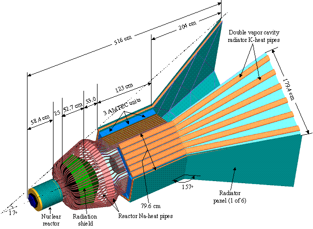
Figure 3. Isometric View of the Scalable AMTEC Integrated Reactor Space Power System (SAIRS-C).
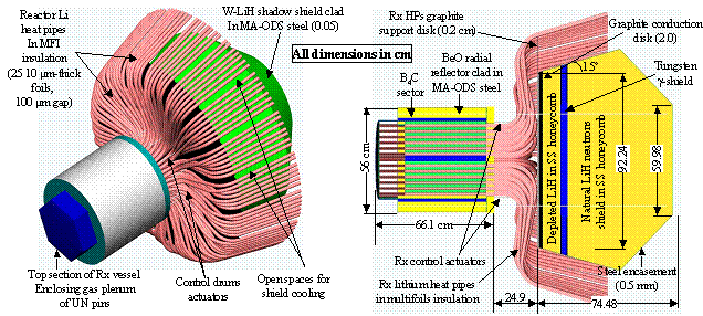
Figure 4. Figure 4. Cross-sectional and Isometric Views of the HP-STMC Reactor and Radiation Shield
- System Simulation & Transient Analysis
- HPTAM
- The Heat Pipe Transient Analysis Model "HPTAM" (Figure 12) was developed at UNM-ISNPS for simulating the transient and
steady-state operation, as well as the startup from a frozen state of alkali-metal and low-temperature heat pipes. Heat pipes are used
in many space nuclear reactor power systems for transporting the reactor's thermal power to the converters (lithium or sodium heat pipes),
transporting the waste heat from the cold side of the converters to the heat rejection radiator (sodium or potassium heat pipes), and/or for
spreading the heat in finned radiator surfaces (potassium, rubidium or water radiator heat pipes). HPTAM has been the subject of continuous
upgrade and verification since the early nineties using experimental data for water, sodium (Figure 13), and lithium (Figure 14) heat pipes.
The fully 2-dimensional and transient HPTAM model (Figure 12) uses the Darcy's extended flow equations to model the liquid flow in the
porous wick and annular space, in conjunction with a fixed-grid, homogeneous enthalpy method to calculate the change of phase in these
zones. HPTAM calculates the radius of curvature of the liquid meniscus in the surface pores of the wick, and couples the vapor and wick
regions with appropriate momentum and enthalpy jump conditions, which allows HPTAM to predict the capillary limit, partial recession of
liquid in the evaporator wick, and pooling of excess liquid in the vapor core. HPTAM also calculates the rates of sublimation of the
frozen working fluid in the evaporator and resolidification in the adiabatic and condenser sections early during the startup from a
frozen state, and simulates the free-molecule, transition, and continuum vapor flow regimes using the Dusty Gas Model.
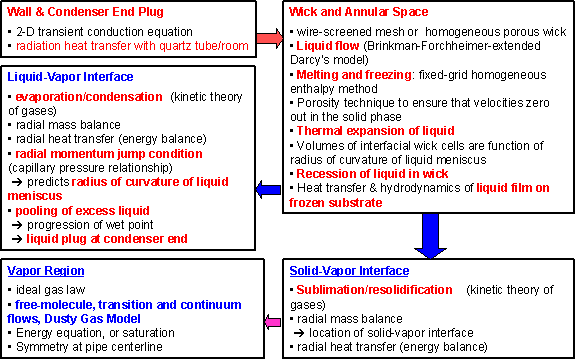
Figure 12. Block-Diagram of HPTAM's Physical Model
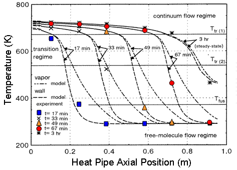
Figure 13. Axial Distributions of Wall and Vapor Temperatures during the Startup of a Sodium Heat Pipe (Faghri et al., 1991)
- AMTEC Performance and Evaluation Analysis Model (APEAM)
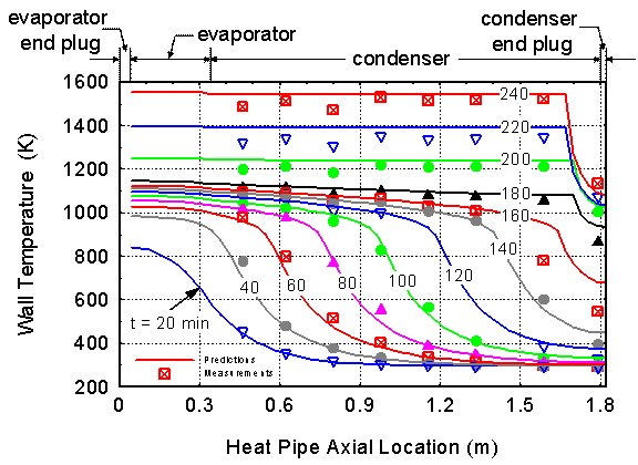
Figure 14. Wall Temperature during Startup of Li Heat Pipe; Symbols Represent TC data at Particular Times (Reid, Sena, Merrigan, Elder and Martinez 1999)
- AMTEC Performance and Evaluation Analysis Model (APEAM)
- In the 1990's, UNM-ISNPS participated in a comprehensive testing and modeling program with the Air Force Research Laboratory's
(AFRL) Space Vehicles Directorate. The objective of this program was to advance the technology of vapor anode, multi-tube Alkali-Metal
Thermal-to-Electric Converters (AMTECs) for flight on future space missions. Each vapor anode, multi-tube PX-series AMTEC cell uses
between 5 and 8 Beta''-Alumina Solid Electrolyte (BASE) tubes, connected electrically in series (Figure 9). The TiN or WRh anode and
cathode porous electrodes are covered with molybdenum mesh current collectors, to minimize internal electric losses. A two-dimensional,
integrated AMTEC Performance and Evaluation Analysis Model (APEAM) was developed at ISNPS, to support ongoing tests at AFRL and improve
the design and performance of sodium and potassium PX-type AMTEC cells. This integrated cell model consists of four major components:
- a. an alkali-metal vapor pressure loss model, which calculates the low vapor pressure at the interfaces between the cathode electrode
and the BASE tube;
- b. a two-dimensional radiation/ conduction heat transfer model, which accounts for all heat exchanges between the different
components of the cell and calculates the temperatures throughout the cell (Figure 10);
- c. a cell electrochemical model, which calculates the effective potential developed across the BASE, due to the isothermal expansion of
alkali metal ions; and
- d. two-dimensional electric circuit model, which determines the electrical resistances of the BASE, electrodes, current collectors,
and conductor leads to the external load, and calculates the cell's electrical potentials, electrode current density, and the cell's total
electrical current. APEAM has been successfully benchmarked against experimental data of individual PX-type converters and of an eight-cell
power generator ground demonstration that were electrically heated (Figure 11).
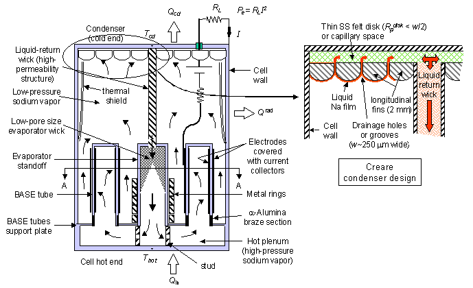
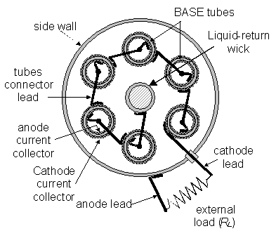
Figure 9. Cross-section views of a typical vapor anode AMTEC converter with 6 BASE tubes connected in series (not to scale)
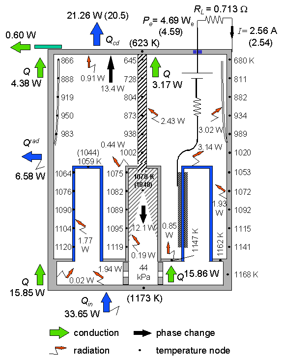
Figure 10. Predicted heat flow and structure temperatures in the PX-3A converter when operating at a peak electrical power of 4.7 We (experimental measurements are shown in parentheses
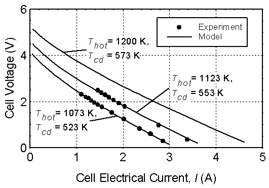
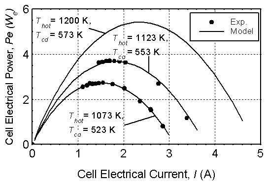
Figure 11. I-V Characteristic and Electric Power Output of PX-3G Cell #1 in Ground-Demo
- DynMo - TE
- ISNPS has developed, using the SIMULINK® platform, the Dynamic simulation Model (DynMo-TE) of Space Reactor Power Systems
(SRPSs) that use a Sectored, Compact Reactor (SCoRe) designed for avoidance of a single point failure, and Thermo-Electric (TE) conversion
(Figure 5). DynMo-TE (Figure 6) is comprised of a number of coupled physical models:
- 1. The SCoRe Model couples a six-points kinetics model to a thermal-hydraulic model of the reactor core (Figure 6). The former
calculates the reactor fission power, subject to the external reactivity insertion at a user specified rate and the temperature-reactivity
feedback for the liquid lithium and UN fuel, and the Doppler reactivity feedback, when applicable.
- 2. The Secondary and Primary Loop Models are coupled thermally in a PCA and a pumps TCA (Figure 6). The coolant flow rates and
pressure losses in the primary and secondary loops are calculated using the mass and momentum balance equations, at the points where the
pressure loss demand-curves intersect the calculated pressure head supply-curves of the EM pumps.
- 3. The Electro-Magnetic (EM) Pump Model calculates the pressure head supply-curve as functions of time and temperature, as function
of the thermal and electrical resistivities of the duct wall material, coolant and copper buses, and the DC voltage and current supplied by
the pumps TCA. The EM pumps use permanent magnets that are thermally insulated from the coolant ducts and maintained well below their Curie
point. The magnet remains saturated by the secondary magnetic flux generated by the electric current passing through the pump ducts.
- 4. The Radiator Panel Thermal-Hydraulic Model couples the 3 radiator segments (one forward and 2 in the rear) hydraulically in parallel
(Figure 5), and discretizes the inlet and outlet flow channels of each segment into small axial sections. Each section comprises a small
number (5 or 6) of rubidium heat pipes with C-C armor and C-C fins, and solves the coupled momentum and energy balance equations for the
coolant flow rate and temperature. The model also calculates the temperature drops in the channel walls and the structure of the evaporator
section of the heat pipes. The radiator model is coupled to a heat pipe model, to calculate the vapor flow and temperature drops in the heat
pipes walls and C-C fins. The heat pipe model also calculates the sonic, capillary, entrainment, and incipient boiling limits.
- 5. The Power Conversion Assembly (PCA) and Pumps TE Converter Assembly (TCA) Models both use a transient performance and
optimization model of the SiGe unicouples. This model is also capable of predicting the performance of segmented TEs, with up to 3
different materials in each leg.
- 6. Accumulator Model: To accommodate the volume changes in the liquid metal coolant in the secondary and primary loops during
transient operation, each loop is equipped with a bellow type accumulator (Figure 6). The accumulator model accounts for the stiffness of
the bellows, in addition to that of the compression spring. For operation redundancy, the cavity above the bellows is filled with inert
gas to support the spring and the bellows in adjusting the coolant pressure in the loops. The accumulator model calculates the transient
changes in the coolant volume in the accumulator, the compression length of the helical spring, and the coolant pressure in the loop.
- DynMo-TE has been used successfully to optimize the design of the SRPS, investigate the effect of using different combinations
of alkali metal coolants (Li, Na, and NaK) in the primary and secondary loops, study the startup transient and propose a startup scenario
to minimize the amount of startup batteries needed, and investigate the load-following operation of the SRPS (Figure 7). DynMo-TE is
particularly well suited for developing safe startup procedures and schemes for adaptive and autonomous operation and control of the SRPS.
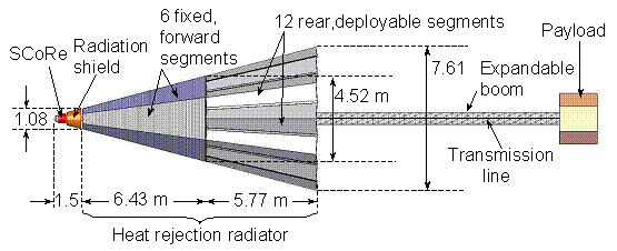
Figure 5. A Layout of SCoRe-TE Space Nuclear Reactor Power System
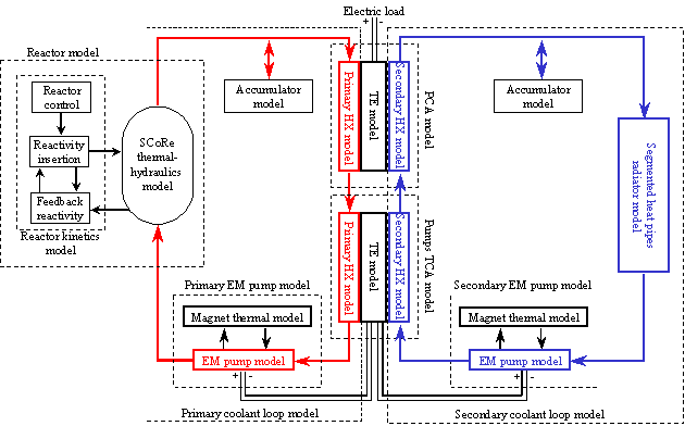
Figure 6. DynMo-TE for Dynamic Simulation of SCoRe-TE SRPS
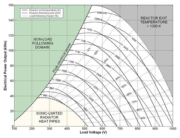
Figure 7. Steady-state Operation Map of SCoRe-TE Power System
- UNM Heat Pipe Model (UNM-HP)
- UNM-HP is a steady-state performance and optimization model of fully-thawed alkali liquid metals (K, Na, and Li) and
water heat pipes. It calculates the vapor pressure losses in the various sections of the heat pipe (evaporator, adiabatic, and condenser),
when vapor flow is dominated by friction rather than inertia forces (vapor Mach number < 0.5). The calculated vapor pressure loss determines
the temperature drop in the vapor core along the heat pipe. This temperature drop is added to the conduction temperature drops in the wall,
liquid annulus, and the liquid saturated wick, both in the condenser and evaporator sections. The sum of these temperature drops gives
the total temperature drop along the heat pipe. UNM-HP accounts for both the inertia and friction forces in the vapor flow, and the vapor
remains saturated. This heat pipe model has been verified successfully using experimental data of the vapor temperature along a short
sodium heat pipe (0.7 m) operated at different powers and Mach numbers up to 0.4 (Ivanovskii et al., 1982; see Figures 15a and 15b).
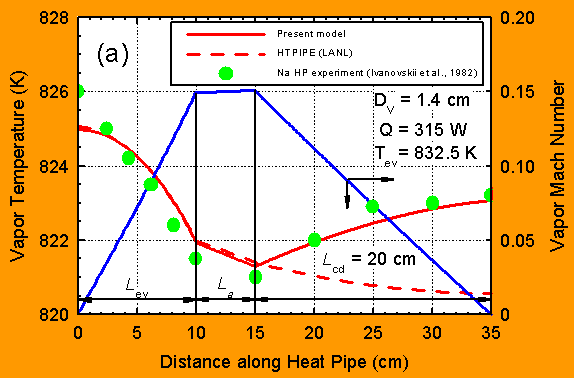
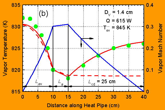
Figure 15. Comparison of UNM-HP Predictions with Measured Vapor Temperatures in a Sodium Heat Pipe at Mach numbers of 0.15 and 0.30 (Ivanovskii et al. 1982)
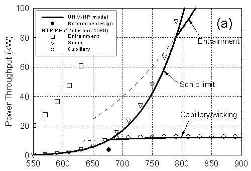
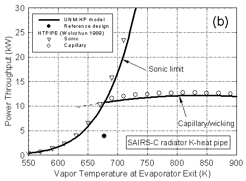
Figure 16. Operation Limits of Potassium Heat Pipe in SAIRS-C Radiator
- he UNM-HP model has been used successfully in the design and thermal analysis of the heat pipes-cooled nuclear reactors and heat
rejection radiator panels of the HP-STMC and SAIRS power systems developed at UNM-ISNPS. In such designs, the local radial and axial vapor
mass fluxes of working fluid in the heat pipe are calculated from the local energy balance, which accounts for the heat input to the
evaporator section and the heat rejection along the condenser section. UNM-HP also accounts for the heat conduction in the C-C fins of
the radiator heat pipes and calculates various heat pipes operation limits; namely, the viscous, sonic, capillary, entrainment, and
incipient boiling, to determine the useful operation domain bound by these limits. Figures 16a and 16b compare the predictions of the
UNM-HP model of the operation limits of the radiator heat pipes in SAIRS-C with those obtained using the widely used HTPIPE model,
developed by Los Alamos National Laboratory (Woloshun et al., 1989). As these figures indicate, the predictions of the sonic and the
capillary/wicking limits by the two models are in good agreement. Figure 17 shows the temperature contours of the SAIRS radiator
surfaces predicted by the model at nominal operation. The Scalable AMTEC Integrated Reactor Space Power Systems (SAIRS, Figure 3)
developed at UNM-ISNPS all use D-shaped potassium heat pipes radiators with C-C armor and fins.
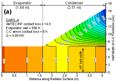
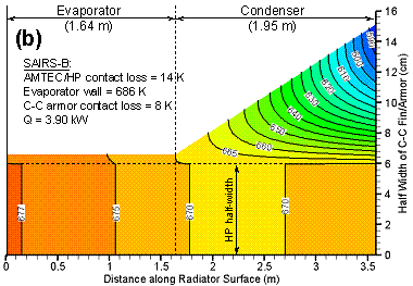
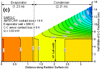
Figure 17. Surface Temperature Contours of SAIRS Radiator C-C Armor/Fin
 Back to The Top