
In the 1990's, UNM-ISNPS participated in a comprehensive testing and modeling program with the Air Force Research Laboratory's (AFRL) Space Vehicles Directorate. The objective of this program was to advance the technology of vapor anode, multi-tube Alkali-Metal Thermal-to-Electric Converters (AMTECs) for flight on future space missions. Each vapor anode, multi-tube PX-series AMTEC cell uses between 5 and 8 Beta''-Alumina Solid Electrolyte (BASE) tubes, connected electrically in series (Figure 34). The TiN or WRh anode and cathode porous electrodes are covered with molybdenum mesh current collectors, to minimize internal electric losses. A two-dimensional, integrated AMTEC Performance and Evaluation Analysis Model (APEAM) was developed at ISNPS, to support ongoing tests at AFRL and improve the design and performance of sodium and potassium PX-type AMTEC cells. This integrated cell model consists of four major components: (a) an alkali-metal vapor pressure loss model that calculates the low vapor pressure at the interfaces between the cathode electrode and the BASE tube. (b) a two-dimensional radiation/ conduction heat transfer model that accounts for all heat exchanges between the different components of the cell and calculates the temperatures throughout the cell (Figure 35). (c) a cell electrochemical model that calculates the effective potential developed across the BASE, due to the isothermal expansion of alkali metal ions. (d) two-dimensional electric circuit model that determines the electrical resistances of the BASE, electrodes, current collectors, and conductor leads to the external load, and calculates the cell's electrical potentials, electrode current density, and the cell's total electrical current. APEAM has been successfully benchmarked against experimental data of individual PX-type converters and of an eight-cell power generator ground demonstration that were electrically heated (Figure 36).
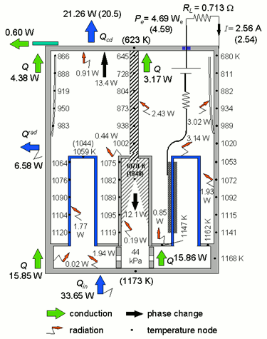
Figure 35. Predicted heat flow and structure temperatures in the PX-3A converter when operating at a peak electrical power of 4.7 We (experimental measurements are shown in parentheses).
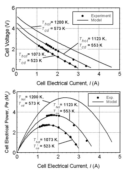
Figure 36. I-V characteristic and electric power output of PX-3G Cell #1 in Ground-Demo.
Back to The Top